The production, propagation, reflection, scattering, and reception of sound in seawater. The sea covers approximately 75% of the Earth's surface. In terms of exploration, visible observation of the sea is limited due to the high attenuation of light, and radar has very poor penetrability into salt water. Because of the extraordinary properties that sound has in the sea, and because of some of the inherent characteristics of the sea, acoustics is the principal means by which the sea has been explored. See also: Ocean
Absorption
Sound has a remarkably low loss of energy in seawater, and it is that property above all others that allows it to be used in research and application. Absorption is the loss of energy due to internal causes, such as viscosity. Over the frequency range from about 100 Hz (cycles per second) to 100 kHz, absorption is dominated by the reactions of two molecules, magnesium sulfate (MgSO4) and boric acid [B(OH)3]. These molecules are normally in equilibrium with their ionic constituents. The pressure variation caused by an acoustic wave changes the ionic balance and, during the passage of the pressure-varying acoustic field, it cannot return to the same equilibrium, and energy is given up. This is called chemical relaxation. At about 65 kHz magnesium sulfate dominates absorption, and boric acid is important near 1 kHz. Absorption has been measured in the laboratory and at sea (Fig. 1). The absorption coefficient α is the exponential loss in intensity of an acoustic signal of a given frequency per meter of its path. The ratio of intensities after traversing a distance r is given by Eq. (1).
Often absorption is defined as the power to the base 10, that is, I/I0 = 10−αr. Due to the very low absorption coefficients in seawater, the convention is to change its units to km−1. See also: Seawater; Sound; Sound absorption
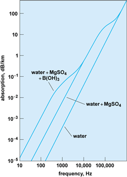
Both magnesium sulfate and boric acid are present in very small amounts in seawater. If their concentrations were a few orders of magnitude larger, sound measurement would be as ineffective as it is with radar or optics.
Sound speed
The speed of sound in seawater and its dependence on the parameters of the sea, such as temperature, salinity, and density, have an enormous effect on acoustics in the sea. There have been several empirical equations published in the literature, differing by small amounts, but for the purposes here, the differences are unimportant. To the lowest order in temperature, salinity, and pressure is Eq. (2),
where the speed of sound in seawater (C) is in meters per second, temperature (T) is in degrees Celsius, salinity (S) is in parts per thousand (‰), and depth (Z) is in meters.
Ocean environment
Generally the environmental parameter that dominates acoustic processes in oceans is the temperature, because it varies both spatially and temporally. The dynamics of the sea are very complex, and one driven by solar heating, winds, atmospheric forces, bathymetry, major ocean currents, turbulence, and the Earth's rotation. It is impossible to include all of these effects in the equations of acoustics. But by limiting the theory to the most salient features, and through reasonable approximations, some solutions can be obtained that are in agreement with experimental results. When agreement is not satisfactory, either the acoustic theory or the ocean model must be modified.
Solar heating of the upper ocean has one of the most important effects on sound propagation. As the temperature of the upper ocean increases, so does the sound speed. Winds mix the upper layer, giving rise to a layer of water of approximately constant temperature, below which is a region called the thermocline. Below that, most seawater reaches a constant temperature. All these layers depend on the season and the geographical location, and there is considerable local variation, depending on winds, cloud cover, atmospheric stability, and so on. Shallow water is even more variable due to tides, freshwater mixing, and interactions with the seafloor. Major ocean currents, such as the Gulf Stream and Kuroshio, have major effects on acoustics. The cold and warm eddies that are spun off from these currents are present in abundance and significantly affect acoustic propagation. See also: Gulf Stream; Kuroshio; Oceanography
Units
The science of underwater sound is the study of pressure waves in the sea over the frequency range from a few hertz to a few megahertz. The International System (SI) units are the pascal (Pa) for pressure (equal to one newton per square meter) and the watt per square meter (W/m2) for sound intensity (the flow of energy through a unit area normal to the direction of wave propagation). In acoustics, it is more convenient to refer to pressures, which are usually much smaller than a pascal, and the consequent intensities with a different reference, the decibel. Intensity in decibels (dB) is ten times the logarithm to the base ten of the measured intensity divided by a reference intensity. The unit of reference intensity is the intensity of a plane wave that has a root-mean-square sound pressure of one micropascal (1 μPa). In the past, several other reference units have been used. See also: Decibel; Sound intensity; Sound pressure
Wave propagation
The mathematical equation that sound obeys is known as the wave equation. Its derivation is based on the mathematical statements of Newton's second law for fluids (the Navier-Stokes equation), the equation of continuity (which essentially states that when a fluid is compressed, its mass is conserved), and a law of compression, relating a change of volume to a change in pressure. By the mathematical manipulation of these three equations, and the assumption that only very small physical changes in the fluid are taking place, it is possible to obtain a single differential equation that connects the acoustic pressure changes in time to those in space by a single quantity, the square of the sound speed (c), which is usually a slowly varying function of both space and time. This known as the wave equation [Eq. (3)],
where p is the acoustic pressure; and the differential operator ∇2, known in mathematics as the laplacian, is, in many underwater acoustics applications, given in either spherical or cylindrical coordinates. See also: Fluid-flow principles; Laplacian; Navier-Stokes equation; Wave equation
Knowing the sound speed as a function of space and time allows for the investigation of the spatial and temporal properties of sound, at least in principle. The mathematics used to find solutions to the wave equation are the same as those that are used in other fields of physics, such as optics, radar, and seismics. See also: Wave motion
In addition to knowing the speed of sound, it is necessary to know the location and nature of the sources of sound, the location and features of the sea surface, the depth to the seafloor, and, in many applications, the physical structure of the seafloor. It is not possible to know the sound speed throughout the water column or know the boundaries exactly. Thus the solutions to the wave equation are never exact representations of nature, but estimates, with an accuracy that depends on both the quality of the knowledge of the environment and the degree to which the mathematical or numerical solutions to the wave equation represent the actual physical situation.
There are a variety of analytical and numerical solutions to the wave equation that are useful. An important parameter in selecting the most appropriate solution is the ratio of acoustic wavelength to some of the characteristic dimensions of the environment. The wavelength λ of a sound wave of frequency f is Eq. (4).
Since the speed of sound is approximately 1500 m/s (5000 ft/s), typical wavelengths for 100, 1000, 10,000, and 100,000 Hz are 15, 1.5, 0.15, and 0.015 m (50, 5, 0.5, and 0.05 ft), respectively.
If the wavelength is very small compared to the dimensions of oceanographic interest (such as depth, distance, seafloor, or sea surface roughness), good approximate solutions are those of geometric optics, known as ray theory. Rays that originate at the source follow paths that are determined by Snell's law. According to Snell's law, if a ray is launched from a source where the sound speed is c0 at an angle θ0 from the horizontal axis, the horizontal angle θ of the ray will, at any point along its path, obey Eq. (5),
where c is the speed of sound at a point along the ray path. This statement allows ray paths to be determined for each angle θ0 by either analytical or numerical computation. A simple example is shown in Fig. 2. As will be seen later, this limit allows for good insight into the spreading and the distribution of acoustic energy. See also: Geometrical optics; Refraction of waves
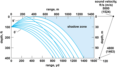
The bending of rays is called refraction. The case shown in Fig. 2 is for a linear sound speed profile. It can be shown for this case that rays will follow circular paths. There will be a limiting ray, as shown, beyond which no ray will exist. The region beyond that ray is known as the shadow zone, and is well known to limit the detectability of objects by sonars. Other, more elaborate solutions to the wave equation are required when geometric distances become comparable to wavelength, such as a sound wave near a boundary or object, or when multiple waves are present. See also: Sonar
The interaction of sound waves with the boundaries of the sea is essential for understanding underwater sound. By examining a highly idealized model, it is possible to gain a valuable understanding of some important properties of the interaction of acoustic fields with the sea surface and seafloor. It is useful to consider the case of a plane sound wave with a frequency f. The second-order derivative with respect to time on the right-hand side of the wave equation (3) yields for that term c−2∂2 p/∂t2 = −4π2 f2 c−2 p. Substituting this into Eq. (3) gives Eq. (6),
which is known as the Helmholtz equation. The quantity k is called the wave number, defined to be k = 2πf/c. If, as shown in Fig. 3, the acoustic wave is directed toward a boundary at an angle θ from the horizontal axis, x, the wave can be represented by Eq. (7),
where A is its acoustic pressure amplitude. There will also be a reflected wave, given by Eq. (8),
whose acoustic pressure amplitude is B. If the medium on the other side of the boundary is also a fluid, but with a sound speed of c0 and a wave number k0, a good “guess” at the solution for a wave traveling away from the boundary, as shown in Fig. 3, is given by Eq. (9),
where D is the acoustic pressure amplitude.
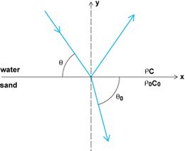
At the boundary, y = 0, there are two conditions that have to be satisfied. The pressure on both sides has to be equal, and the vertical component of the fluid displacements has to be continuous, for all values of x. It is therefore required that k cos θ = k0 cos θ0, or, remembering the definitions of k and k0, cos θ/c = cos θ0/c0, which is identical with the Snell's law of Eq. (3). Returning to the conditions that have to be met at y = 0, from the continuity of pressure, Eq. (10)
must be satisfied.
A fluid's vertical velocity, uy, can be shown to obey Eq. (11),
where ∂p/∂y is the local vertical pressure gradient, and the density is ρ. In the upper fluid, at the boundary the total pressure is p = pi + pr. Taking the time derivative of uy in both fluids to be equal at y = 0 leads to Eq. (12).
Dividing Eq. (12) by Eq. (10) leads to Eq. (13)
for B, where Z = ρ0 c0/ρc.
In the case of reflection from the air-sea surface, typical approximate values for the densities and sound speed for air and water, respectively, are 1.25 kg/m3 (0.078 lb/ft3) and 300 m/s (1000 ft/s), and 1000 kg/m3 (62 lb/ft3) and 1500 m/s (5000 ft/s). Therefore, Z is approximately 2.5 × 10⁻⁴. It can also be shown from Snell's law that sin θ0 will, for this case, always be a number close to 1. So the amplitude of the reflected wave will be almost exactly that of the incoming wave, only having the opposite sign. The sum of the amplitudes at the boundary of the incoming wave, pi, and the reflected wave, pr, is very close to zero. This boundary is called a pressure release boundary and is approximated as p = 0. Since A ≈ B, it is also evident from Eq. (10) that very little energy is transmitted to the air.
A typical sandy seafloor has a sound speed approximately 10% higher and a density about twice that of seawater. From Snell's law it can be seen that at the angle θ = arccos (c/c0) ≅ 25° the direction of the refracted wave in the seafloor is parallel to the boundary. At that angle, it can be seen that B = A. That is, all of the acoustic energy is reflected. For angles θ < 25°, values of sin θ0 become purely imaginary and B can be shown to be equal to A times a term that only represents a phase change. The term B/A is known as the reflection coefficient, and the angle θc = arccos (c/c0) is called the critical angle. This concept of total reflection is essential to the understanding of propagation in shallow water. It can be shown that the reflection is a minimum at normal incidence, implying that this is also the angle of maximum penetration into the seafloor and therefore important in the use of acoustics in the study of the internal structure of the seabed.
Although these two idealized examples do not represent the actual conditions of the sea, they do contain some of the physics that is observed. The sea surface is rarely flat, but it is always considered to be a pressure release surface. The seafloor is never a perfect fluid, and more realistic model extensions include absorption, viscosity, shear, and layering. The theories follow the same rules, namely, finding solutions in each medium and matching the boundary conditions of continuous pressure and displacement. See also: Reflection of sound
Deep-water propagation
During the middle years of the twentieth century, it was discovered that low-frequency sound, under some conditions, could propagate over very long distances with unusually small losses in intensity. Indeed, explosive signals were heard halfway around the Earth. The concept can be understood through the application of ray theory in deep water. Since the deep oceans are several thousand meters deep and major oceanographic features have dimensions many times larger than acoustic wavelengths, the use of geometric optics, or ray theory, is appropriate.
In many parts of the world, warm water overlays the deeper cold water. Sound speed near the surface can be dominated by the temperature, which is highest at or near the surface, and then decreases with depth until it becomes constant, in most oceans somewhere near 4°C (39°F). From Eq. (2) it can be seen that the effect of temperature is to decrease sound speed with depth, and the pressure term (0.016 Z) causes an increase with depth. The sound speed profile as a function of depth (due to the temperature and depth) will have a minimum that is usually found to be at about 1000 m (3300 ft). An idealized picture is shown in Fig. 4.
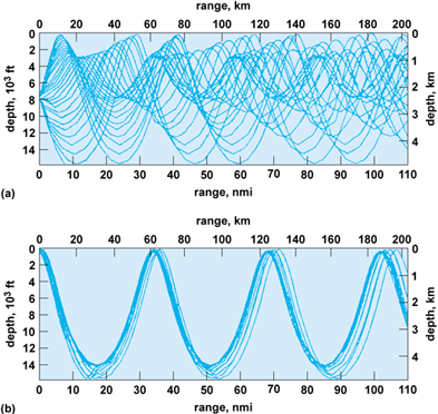
For an impulsive omnidirectional sound source (typical of an explosive) that is located in depth at the minimum sound speed (Fig. 4a), rays are emitted in all directions and each will follow a trajectory dictated by Snell's law. Those that are directed upward will gradually bend downward as they approach water with higher speeds. Those with steep enough trajectories will strike the sea surface. There will be a limiting ray that reaches the surface at zero degrees. Its angle of emission from the source, using Snell's law, is given by Eq. (14).
All rays with smaller angles of emission will not reach the surface, and will bend toward the axis of minimum speed, intersecting the axis with the equal but opposite sign to that at which they were emitted. If the sound speed at the surface is less than that at the bottom, these rays will not reach the bottom as shown in Fig. 4. The same is true for the down-going rays. There will be a limiting ray with an angle again dictated by Snell's law, and rays that do not interact with either the surface or the seafloor and propagate outward from the source cylindrically rather than spherically.
The path that each ray will follow can be determined using Snell's law and the sound speed profile. (There are many computational methods available for this.) For a given range, it is possible to determine the family of rays that can be emitted from the source and pass through that point. It is also possible, knowing the ray paths, to compute the arrival time of each. It can be shown that the rays that arrive first are those that make the largest excursions from the channel axis, and the last to arrive is the ray that travels along the channel axis, which will be the most intense. The signal that is received on the channel axis from a distant explosive source begins with weak arrivals from the rays making the widest excursions and ends with a dramatic buildup that suddenly cuts off with the arrival of the ray that travels along the channel axis. The arrival of this last signal can give an accurate determination of the range from the source to the receiver, and is the basis for the SOFAR concept that was used for the location of downed aircraft in earlier times. See also: Sofar
For a sound source located near the surface, the rays that propagate without interaction with the surface or seafloor are more limited and leave large regions where sound does not penetrate (Fig. 4b). These shadow zones are vast, and it is only after large distances that the rays arrive near the surface. This sinuous behavior of the sound energy continues for very long distances with cyclic intervals of approximately 60–70 km (37–44 mi). The areas where there is focusing near the surface are called convergent zones. These are important for the detection of distant signals.
Of interest to the oceanographers and acousticians is the application of long-range, deep-water propagation to the study of ocean structure, such as warm and cold water eddies, the meander of ocean currents, internal waves, and global warming. For a fixed geometry of sources and receivers there will be specific ray paths, each migrating through the upper and lower depths. The arrival time of each ray is determined by the path and the sound speed along it. Experiments have shown remarkable temporal stability in many of the paths By observing the angular direction and arrival times, the paths of the arrivals can be identified. The measurement of small changes in the arrival times can be used to interpret oceanographic change. It is a form of tomography. See also: Computerized tomography
There are many other mathematical solutions to the wave equation that are used in deep-water application. In order to obtain tractable solutions, many of these require assumptions about the homogeneity of the ocean. Of particular merit is the application of the parabolic approximation to long-range propagation for the case where there is a horizontal variation in oceanographic conditions. In most ocean applications, it is a valid to assume that the horizontal change in sound speed is sufficiently gradual to allow the range-dependent part of the Helmholtz equation to be approximated by a parabolic equation. The method is highly amenable to modern computation, and has been applied to many problems in acoustics, including shallow-water and atmospheric acoustics. See also: Differential equation
Shallow-water propagation
Shallow water can be defined as the regions of the oceans associated with the continental shelves. Shallow depths are of the order of a few hundred meters or less. Unlike deep water, the seafloor plays a major role in the acoustic properties in shallow water. In shallow water, the application of higher frequencies is more suitable for both the detection of objects and for the study of some of the smaller-scale oceanographic processes. For lower frequencies, propagation over longer ranges requires the consideration of the many acoustic paths contributed by the continued interaction with the boundaries. Sound that reflects off the sea surface loses little energy. The reflections off the seafloor when the grazing angle is greater than critical are also nearly perfectly reflecting. Thus the sound field at longer ranges comprises many arrivals.
The principal method of solving the wave equation in shallow water is that of normal modes. The approach is to make the assumption that sound propagation in the ocean has no azimuthal dependence. Then the wave equation, or the Helmholtz equation, depends only on range and depth, and is separable into an equation of depth and one of range. The sound speed is assumed to have no range dependence, but it can depend on depth.
The range-dependent equation is the Bessel equation, whose solutions are well known. The vertical, or depth-dependent equation, is then solved. It will depend on the sound speed profile, the water depth, and the boundary conditions at the sea surface (the pressure release condition) and the seafloor. This leads to a set of solutions, called modes. Then, by representing the source, often as a point source at a depth z0, the solution is obtained for any point in the water column by a sum of modes. Range dependence is difficult to accommodate to this method, but the normal-mode method is a very powerful tool for understanding the complex way that signals travel through shallow water. Signals become distorted from their original form due to the changes in horizontal speed that result from the complex interaction of sound with the boundaries. The frequency dependence of sound speed is called dispersion. See also: Bessel functions
Ambient noise
A consequence of the remarkable transmission of sound is that unwanted sounds are transmitted just as efficiently. One of the ultimate limitations to the use of underwater sound is the ability to detect a signal above the noise. In the ocean, there are four distinct categories of ambient sound: biological, oceanographic physical processes, seismic, and anthropogenic. Seismic is in the frequency range called infrasound, and will not be covered. See also: Infrasound
Biological sources
Biological sound is caused by both fish and marine mammals for the purpose of either communication or predation. The frequency range is broad. The sounds are sometimes very intense and geographically variable. At the low frequencies (those that would be called audible), the sounds of whales and other mammals dominate. Many of the species are migratory, giving rise to very high sound levels at certain times of the year at specific locations. There are currently intense studies of these creatures with the objective of assessing their numbers, their habits, and the purposes of their communications. At the higher frequencies, about 1–20 kHz, snapping shrimp dominate the sound in shallow water, especially around piers and other structures. From an engineering viewpoint, it is difficult to conceive of methods, other than avoidance, to process against these noises due to their high variability in space and time.
Physical processes
The natural physical causes of ambient noise are the sounds of breaking waves, surf, and rain noise.
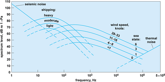
There have been only a few studies of the physical mechanisms that create the sound. In the few measurements that have been made on individual breakers, there appears to be a wide variation in the frequency content. A plausible hypothesis is that the collapsing of the bubble cloud produced by the breaking wave generates a band of acoustic frequencies. This, however, has not been confirmed. Because winds are the general cause of breaking waves, this type of noise is referred to as wind-generated. It dominates the noise spectrum above about 500 Hz, but is a contribution down to at least 100 Hz. Wind-generated noise increases with wind speed, with the difference in level being about 30 dB between a very calm sea (sea state 1) and a violent sea (sea state 6). See also: Ocean waves
Anthropogenic sound
Shipping dominates the ambient sound in most oceans in the frequencies of about 10–150 Hz. The level clearly depends on the amount and type of shipping and the propagation conditions. The radiated noise from each class of ship is different, with the loudest being supertankers. Another anthropogenic sound, from oil prospecting, is seasonal and geographically limited, but the airguns and sparkers used have very high source levels.
Figure 5 shows an averaged compilation of typical sound levels that are due to anthropogenic and natural physical sounds. See also: Acoustic noise
Scattering and reverberation
The other source of unwanted sound is reverberation. Sound that is transmitted inevitably finds something to scatter from in the water column, at the sea surface, or at the seafloor. The scatter is usually in all directions, and some of it will return to the system that processes the return signals. Sources of scattering in the water column are fish, particulates, and physical inhomogeneities. The sea surface is, under normal sea conditions, agitated by winds and has the characteristic roughness associated with the prevailing atmospheric conditions. Rough surfaces scatter sound with scattering strengths that depend on the roughness, the acoustic frequency (or wavelength), and the direction of the signal. The scattering is highly time-dependent, and needs to be studied with an appropriate statistical approach. The seafloor has inherent roughness and is usually inhomogeneous, both properties causing scatter. Although scatter degrades the performance of sonars, the characteristics of the return can be determined to enable its cancellation through signal processing or array design. Scattering can also be used to study the sea surface, the seafloor, fish types and distribution, and inhomogeneities in the water column. See also: Scattering layer
There are still fundamental questions about the scattering of sound from the sea surface. At higher wind speeds, the classic theory of scattering from the sea surface underestimates the scattering strength by several decibels, enough to question either its validity or applicability. There is evidence that the layer of bubbles caused by the breaking of waves plays a significant role. Conclusive experimental proof of this hypothesis has not been obtained. The seafloor needs more study to determine the causes of scattering. That, however, may not yield a universal model because of the widely varying nature of the seafloor.
Experiments and ships
Both oceanography and ocean acoustics (underwater sound) have gained enormously from the developments in electronics, miniaturization, materials, and digital processing. It is now possible to place measuring instruments in the sea: on a buoy (either free-floating or tethered), on an anchored platform anywhere in the water column, or on underwater vehicles. The miniaturization of processing and data storage allows for the collection of large databases in real or near-real time. Communications now allow the dissemination of data to many locations at any distance. See also: Instrumented buoys; Underwater vehicles
Underwater acoustic instrumentation, whether for basic science studies, the detection of objects in the sea, or the exploitation of nature's resources, can be divided into active and passive types. Active measuring systems send and receive signals. Passive systems only receive signals. The active systems currently use everything from explosives and airguns, which create high-energy short pulses at characteristically low frequencies, to small hand-held systems with ultrahigh frequencies.
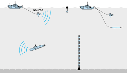
An acoustic signal is usually created by the dilatation of either magnetostrictive or piezoelectric materials. The design for their use is dictated by the desired energy, frequency, and directivity (beam width). The most common materials used for the reception of signals in both active and passive systems are piezoelectric. The receivers are commonly called hydrophones. Significant gains can be achieved in signal level by geometrically arranging sets of hydrophones or transmitting elements with the proper spacing. These are called arrays. Modern electronics and digital processing allow for many hydrophones to be placed in an array that can be towed from a ship, deployed horizontally, suspended horizontally from a stationary ship or platform, or suspended from an anchor. Figure 6 depicts some of these concepts. Sources can be fixed or towed and, in some cases, mounted on platforms such as the ship's sonars and depth finders. See also: Acoustic signal processing; Hydrophone; Magnetostriction; Parametric array; Piezoelectricity
The common requirement of all oceangoing research is a ship to carry equipment, scientists, and engineers to the site of an experiment, to deploy the instruments, maintain station, and to run on specifically determined routes. The planning and logistics for ocean experimentation are a vital part of the experience. The ships that are used for deep-sea work must be capable of withstanding storms and robust enough to be functional for the completion of experiments under difficult conditions. Nearshore operations usually do not have the same requirements. Often overlooked is the cost and tempo of working at sea. While ocean instrumentation has improved and its costs have dropped, the price of ships and the cost of operation have increased significantly. Although modern oceanographic vessels are much more capable than those of the past, they still sail at speeds of only a few knots. Seagoing is still a labor-intensive endeavor that cannot be overlooked in the planning of experiments. Sometimes aircraft are used for the deployment of sources and sensors. They are excellent within the limitations that are inherent in work with aircraft such as those on weight and volume. See also: Oceanographic vessels


