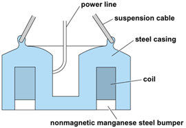
A soft-iron core that is magnetized by passing a current through a coil of wire wound on the core. Electromagnets are used to lift heavy masses of magnetic material and to attract movable magnetic parts of electric devices, such as solenoids, relays, and clutches.
The difference between cores of an electromagnet and a permanent magnet is in the retentivity of the material used. Permanent magnets, initially magnetized by placing them in a coil through which current is passed, are made of retentive (magnetically “hard”) materials which maintain the magnetic properties for a long period of time after being removed from the coil. Electromagnets are meant to be devices in which the magnetism in the cores can be turned on or off. Therefore, the core material is nonretentive (magnetically “soft”) material which maintains the magnetic properties only while current flows in the coil. All magnetic materials have some retentivity, called residual magnetism; the difference is one of degree. See also: Magnetization
A magnet, when brought near other susceptible material, induces magnetic poles in the susceptible material and so attracts it. A force is developed in the susceptible material that tends to move it in a direction to minimize the reluctance of the flux path of the magnet. The reluctance force may be expressed quantitatively in terms of the rate of change of reluctance with respect to distance. See also: Magnetism
In an engineering sense the word electromagnet does not refer to the electromagnetic forces incidentally set up in all devices in which an electric current exists, but only to those devices in which the current is primarily designed to produce this force, as in solenoids, relay coils, electromagnetic brakes and clutches, and in tractive and lifting or holding magnets and magnetic chucks.
Electromagnets may be divided into two classes: traction magnets, in which the pull is to be exerted over a distance and work is done by reducing the air gap; and lifting or holding magnets, in which the material is initially placed in contact with the magnet. For examples of the first type See also: Brake; Clutch; Relay; Solenoid (electricity)
Examples of the latter type are magnetic chucks and circular lifting magnets. The illustration shows a typical circular lifting magnet. The outer rim makes up one pole and the inner area is the opposing pole. The coil is wound cylindrically around the center pole. Manganese steel, used as a protective cover plate for the coil, is nonmagnetic and thus forces the flux through the magnetic member being lifted.

The mechanical force between two parallel surfaces is given by Maxwell's equation, shown below,
where B is the flux density (in webers/m2), A is the cross-sectional area (in m2) through which the flux passes, and μ0 is the permeability of free space (4π × 10-7 henry/m). When two poles are active, the force produced by each is calculated to find the total force. An interesting result of this relation is that the force is not simply the result of the total flux (BA) but also of the flux density. Thus if the same flux can be forced through one-half the cross-sectional area, the net pull will be doubled. In practice it is difficult, if not impossible, to calculate the actual lifting capacity of the magnet by using Maxwell's equation since the capacity varies with the shape and kind of material lifted, how the material is stacked, and other factors. Therefore, lifting magnets are usually rated on their all-day average lifting capacity.
Since currents are large and the circuit is highly inductive, control of a lifting magnet is a problem. If the line switch were simply opened, a destructive arc would result due to the coil's inductance not allowing the current to change instantaneously to a zero value. Therefore, the controller employed with a lifting magnet usually does the following things automatically: (1) reduces magnet current after an initially high value to a lower holding value to reduce heating of the magnet, (2) introduces a shunt discharge resistor across the magnet coil before allowing the line to be opened when the operator turns the magnet off, and (3) causes a reduced current of reverse polarity to flow in the magnet coil for a short time after the operator turns the switch off. Thus the residual magnetism is canceled and scraps and small chunks that might have continued clinging to the magnet are released.


