Key Concepts
The extraction of kinetic energy from the wind and conversion of it into a useful type of energy: thermal, mechanical, or electrical. The use of wind energy by various devices to propel ships, pump water, grind grains, and perform other energy-intensive tasks has existed since the early Egyptians. The nineteenth and twentieth centuries brought fossil fuels and fossil-fuel engines, and wind had a minor role as an energy conversion source. Only since the oil embargo of 1973 has wind been rediscovered and started to emerge as an important energy source. Advances in large airfoil structure manufacturing, composite materials, computational aerodynamics, and machine design and control have produced larger, lighter, and more efficient and reliable wind energy power systems than ever before. Wind energy represents a growing percentage of the electricity grids of countries worldwide (Fig. 1). See also: Electric power generation; Energy sources; Wind
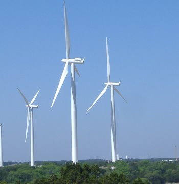
Growing concerns about carbon dioxide (CO2), global warming, and fluctuating fossil fuel prices, make wind energy very attractive. Its principal advantages include zero fuel cost, nondepleting supply, and minimal environmental impact. Also, wind systems are made of components that can be installed quickly, which will have cost benefits from future manufacturing improvements and increased volume. The main engine of current wind electric power development is the modern wind turbine. See also: Global climate change; Turbine
Turbine configurations and components
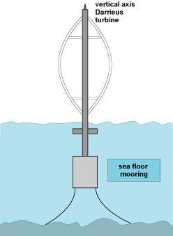
Over time, many different wind energy conversion devices have been used, with most falling into two classes—horizontal or vertical—depending on the rotation axis of the blade rotor (Figs. 1 and Fig. 2). Among these, the horizontal three-blade system of Fig. 1 is the configuration of choice for large wind-power producers. This is an upwind system with the rotor plane in front of the tower and a yaw system to keep the rotor into the wind. The rotor rotation speed is typically 20–50 rpm, and this must be geared up to 1000–3000 rpm to meet the requirements of the electric generator. See also: Generator
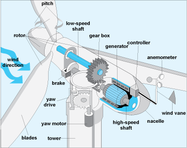
Immediately behind the rotor hub is an enclosure (the nacelle) that houses the drive train and control components (Fig. 3). The drive train consists of a low-speed shaft connecting the rotor to a two- or three-stage gearbox, followed by a high-speed shaft connected to the generator. In addition, there are extensive onboard controls that can change the orientation (or pitch) of the rotor blades, control the yaw, drive-train, and power components; and brake the rotor in possible runaway situations, such as high winds and power-grid outages.
Wind energy basics
Wind turbines are devices that convert wind kinetic energy to rotor shaft mechanical energy to produce electric energy through an onboard electric generator. The amount of wind power captured in this process is directly proportional to the product of the mass flow rate and the kinetic energy of the wind moving through the swept rotor area, as shown in the equation
where ρ is the wind density, A the swept area, Vw the approaching wind velocity, and Cp the power coefficient representing the fraction of the wind energy captured by the turbine rotor. Early studies by A. Betz of ideal stream flows and wind energy converters indicate a maximum possible Cp of 0.593. Although the Betz analysis is oversimplified, it gives a framework for analyzing conversion levels of real systems, where the predictions of Cp are more complex. See also: Energy
The equation indicates that wind power increases directly with the swept area of the turbine A, or the square of the rotor radius. For this reason, rotor blade lengths continue to increase over time. In 1999, maximum blade lengths were about 20 m; they are approaching 90 m, with 100–120-m blades on the horizon. Also, the cube effect of the wind speed in the equation is critical in wind farm siting, since even a 10% advantage of one site over another in wind speed represents a 33% advantage in wind power.
Aerodynamic effects
A wind turbine has many functional elements, but none is more important than the rotor and its ability to convert the maximum amount of the available wind power, maximizing Cp. This is the domain of turbine blade aerodynamics. See also: Aerodynamics
In Fig. 4, the effects of aerodynamic forces on a section of an airfoil rotor blade are illustrated, where the rotor is moving in the vertical plane. The orientation of the blade to the vertical rotation plane is given by the pitch angle θ. As the blade rotates, it experiences not only the effects of the horizontal wind at speed Vw, but also a headwind of magnitude U from the rotation of the blade. As a result, relative to the blade, the wind is approaching at an angle of attack α at a relative speed of Vr. Here, the specific values of α and Vr depend on U/Vw , with α increasing (decreasing) as Vw is increased (decreased) relative to U. See also: Airfoil
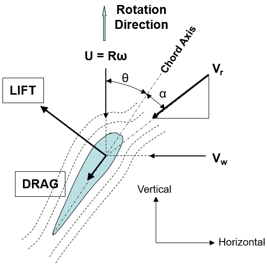
As the wind moves over the rotating blade, the blade experiences (1) a viscous drag force along the angle of attack and (2) a perpendicular lift force arising from flow-induced pressure differences across the upwind and downwind surfaces of the blade. As shown in Fig. 4, the lift force has a positive component in the direction of rotation and is sufficiently large to overcome the negative component of the drag force in this direction. The difference of these components is what drives the blade rotation and provides the torque that ultimately drives the electric generator. See also: Aerodynamic force; Torque
The analysis of such aerodynamic effects on the turbine rotor blades is at the heart of turbine rotor design and ultimately leads to rotor performance characterization in terms of the power coefficient Cp. Current horizontal turbine rotors have Cp values approaching 0.5 compared to the Betz ideal value of 0.583. In general, high power coefficients are associated with high lift-to-drag ratio blade designs and designs that minimize the negative effects of the tip vortex wake.
Turbine performance and operation
Because of the cubic effect of wind velocity on power conversion (see conversion equation above), wind speeds commonly produce rotor power inputs in excess of the rated capacity of the turbine generator. To avoid this, modern wind turbines have controlled actuators to adjust the blade pitch and change the angle of attack, which adjusts the shaft power inputs (Fig. 4).
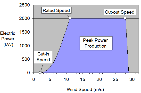
Figure 5 shows a typical power curve for a turbine operated between the cut-in and cut-out speeds. Below the cut-in speed, there is insufficient torque to drive the generator. Above the cut-out speed, the wind loads could cause damage to the turbine components. Between the cut-in and rated speeds, the curve follows the conversion equation; above the rated speed, the pitch actuators are operable and keep the power output constant.
Turbine blade loads and fatigue
During rotation, the cyclic loads on turbine blades arise from several effects. First, because of ground shear effects, the wind speed increases with height. For turbine heights and rotor sizes today, this can mean a 20–30% difference in wind speed from the top of the rotor to its bottom. The corresponding drag and lift force differences would be even greater because of their nonlinear, high-power exponent dependence on Vr. These would be cyclic loads with frequencies of ω. Cyclic loads of similar frequency also arise from stationary and bow wakes of the tower, as well as from gravitational effects that cause cyclic bending moments on the blades.
Any fluctuations in the mean wind speed or turbulent bursts and vortices will expose the blades to a spectrum of loads and frequencies. When combined, all of these effects cause dynamic axial bending and torsional loads, simultaneously acting on the blades, and the frequencies can be much wider than simply ω. In a 20-year period with 4000 h of operation per year, the ω cyclic loads alone would expose the turbine blades to about 108 load cycles.
Exposure of material elements to such cyclic loads over long periods and load cycles can cause material fatigue and eventual failure, if the loads and load cycles are sufficiently large. The failure mechanism involves the formation of microcracks in stress concentration areas that grow into macrocracks, which ultimately lead to fracture surfaces and material failure.
Historically, turbine blade fatigue failure has been the primary failure mode of wind turbine systems. These failures can stem from flawed designs (excessive stress concentrations in areas that are not sufficiently reinforced) or from manufacturing and handling defects, including those created during long-distance transportation and installation. Even small material “bruises,” which are not easily detected visually, can be the origins of premature fatigue failure.
Turbine blade materials
Turbine blades are similar to aircraft wings, with an airfoil shell and internal support structures, which include longitudinal spars and other support elements (including transverse stiffeners and ribs) in critical stress areas. The spars are generally either special I-beam, channel, or box-shape web configurations that span the void between the upper and lower surfaces of the blade shell.
The airfoil shell materials are advanced glass fiber composites, with epoxy, polyester, or vinylester thermoset polymers as the continuous matrix. In addition, pre-prepared high strength-to-weight ratio composite sandwich sheets, with fiberglass and high-strength carbon fibers, are bonded to the shell in high-stress areas and often between the shell and the spar surfaces. Polyurethane foams are often used in these sandwich sections to lower the weight and, in some cases, to fill much of the airfoil core. See also: Composite materials; Polyester resins; Polyether resins; Polyurethane resins
The turbine blade shells and spars are manufactured in large-scale spin-coating and molding processes. Often the spars are spin-coated as in Fig. 6a. Here the fibers and fiber mats or fiber cloth sheets are impregnated with the liquid thermoset, spun onto the spar, and heated to cure the thermoset. Such processing is very efficient and produces very strong elements.
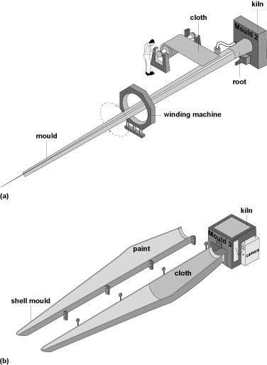
The blade shells are typically molded in upper and lower cavities, with the fiberglass mats or prepregs laid in first (Fig. 6b). Various methods are used to apply the thermoset, some involving repetitive hand layout and coating and others using vacuum or other methods, where the liquid thermoset is infused into the mold and the fiber mats. Thermal curing then follows, which produces the rigid shells. The spar and the sandwich sheets are then bonded in place to complete the blade. Since bonding surfaces are often the locations of fatigue failure, some manufacturers avoid this two-shell bonding by infusing the thermoset into a one-piece shell mold. The challenge of the latter is preventing incomplete thermoset infusion.
The layup and bonding steps are typically done by hand, and thus are always susceptible to quality-control issues and associated defects. Even in the vacuum infusion processes, voids can occur from incomplete infusion or nonuniform curing from the exothermic thermoset reactions. These defects are often not detected before the blades leave the plant and can compromise the blade over time under dynamic loading. Such occurrences indicate the need for continuous improvement of the designs and the associated manufacturing processes.


